Please read this tutorial carefully before doing it, it's a bit long.
Difficulty: ★★☆☆☆
Total time: about 15-20 minutes.
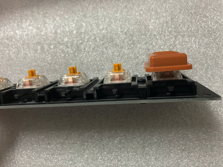
Golden switch axis circuit board, suitable for 3 finger players;
Brown switch axis circuit board, suitable for 4 finger players;
The above is for reference only.
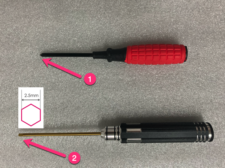
1 Tools list.
①Phillips screwdriver (preferably with magnetic);
②2.5mm hexagon socket screwdriver;
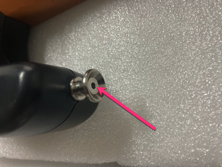
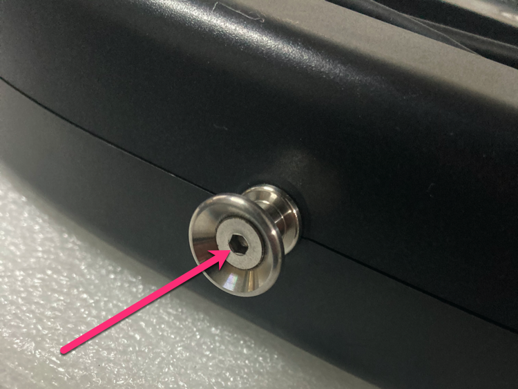
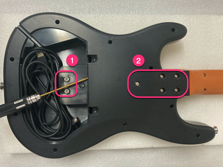
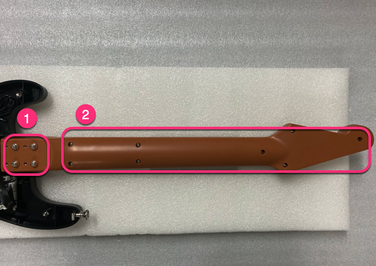
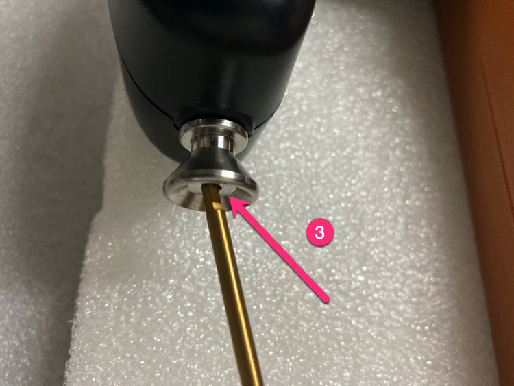
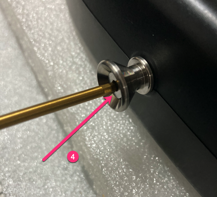
2 Use a 2.5mm hexagon socket screwdriver to loosen the 2 screws at the strap position. Be careful not to unscrew it, just loosen it.
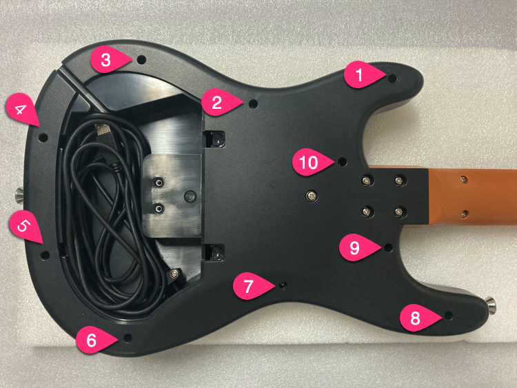
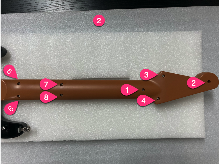
3 Follow the order in the figure, unscrew the screws.
4 Unscrew 10 screws.
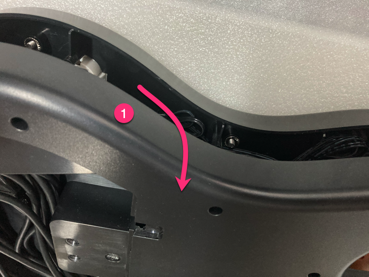
5 Steps to open the bottom cover.
①Open from the upper part of the bottom shell;
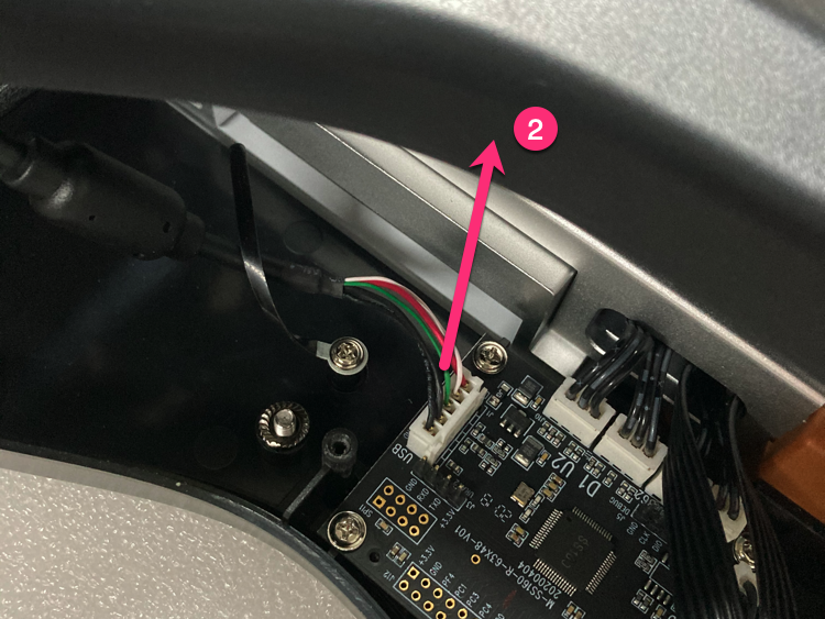
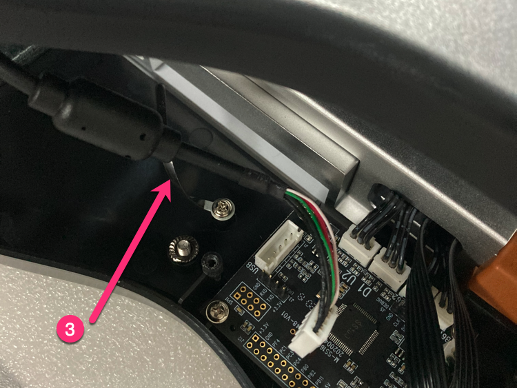
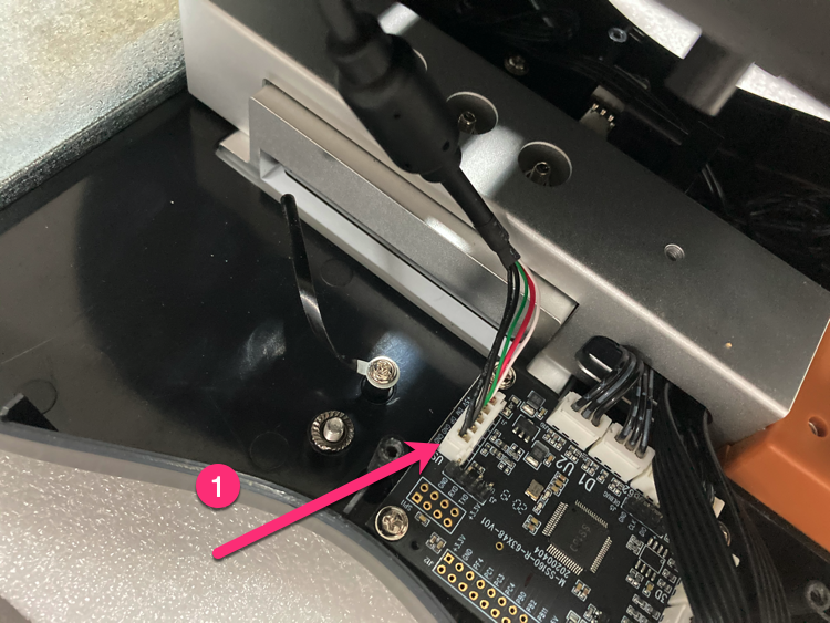
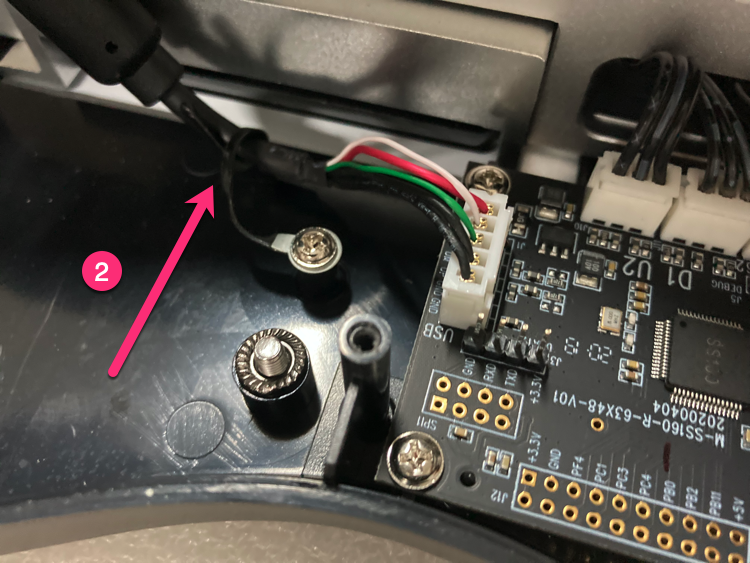
②Unplug the 5PIN USB cable;
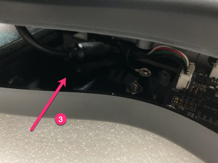
③Loosen the line clip that fixes the USB cable;
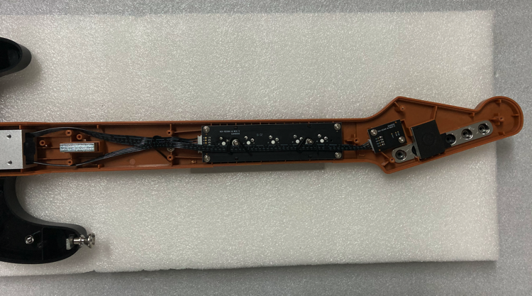
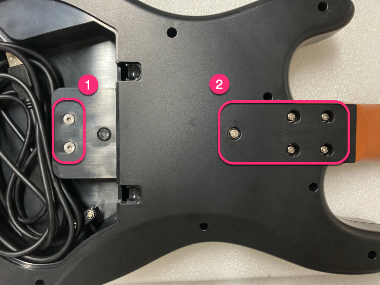
6 Remove the screws by order.
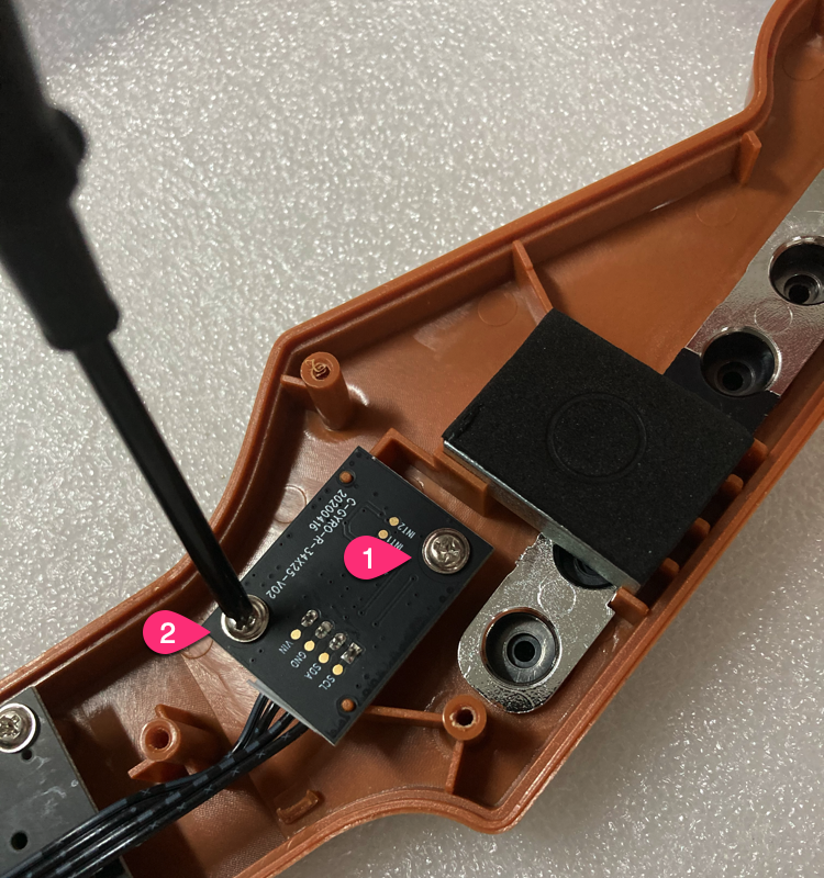
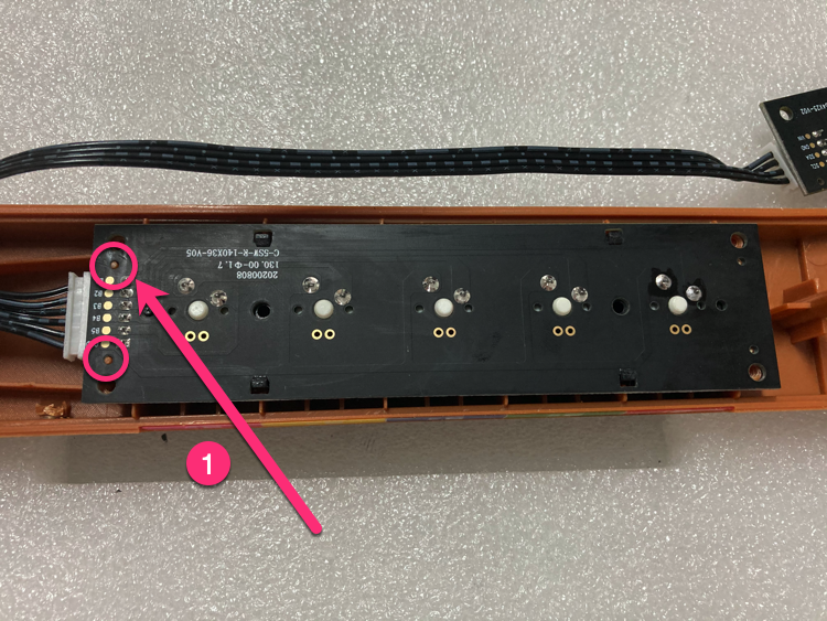
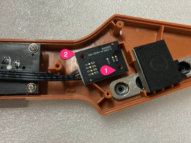
7 Unscrew the 2 screws of the gyro PCB.
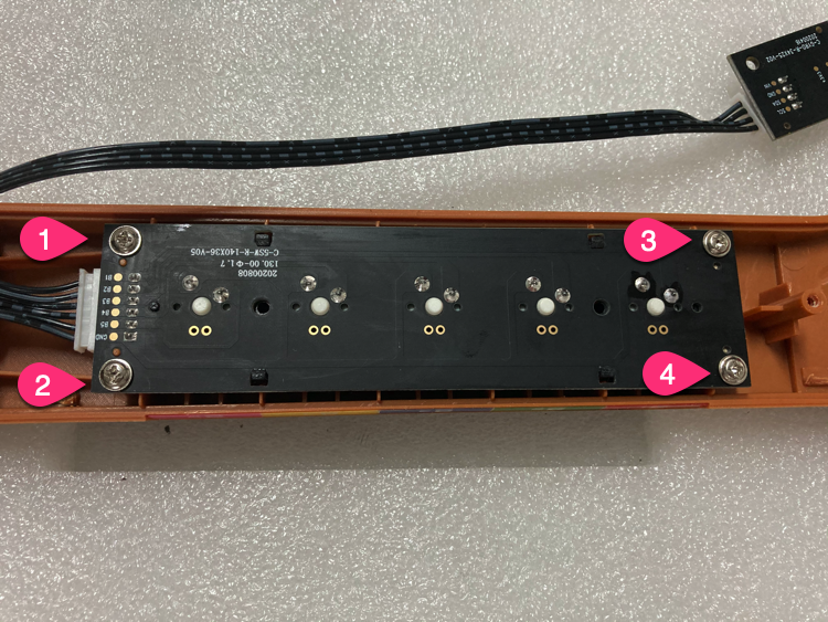
8 Unscrew the 4 screws of the shaft PCB.
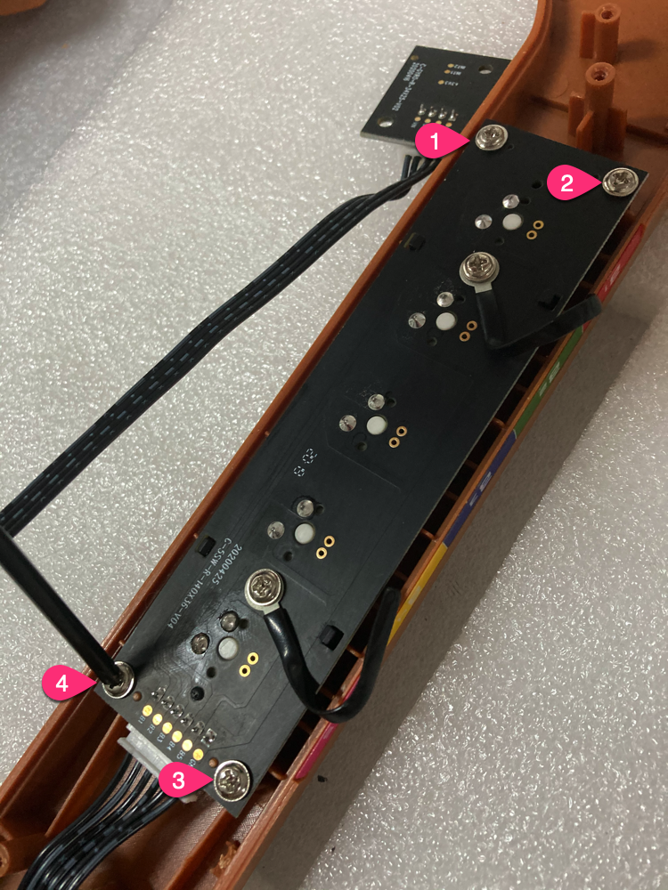
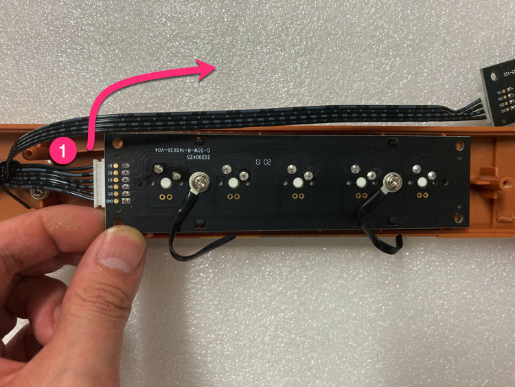
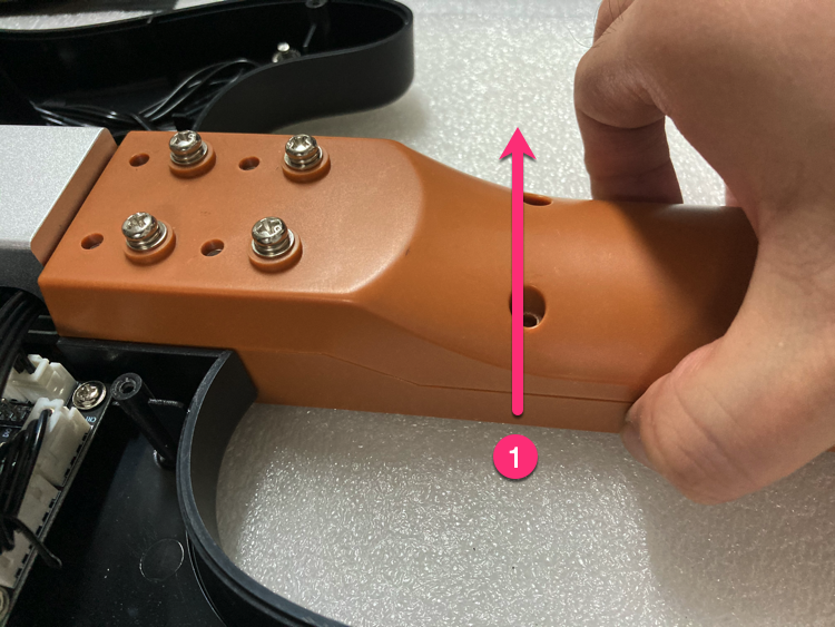
9 Take out the shaft PCB and remove the 6PIN wire.
①From this position, push upward;
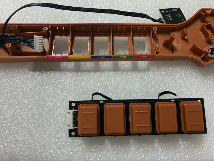
10 Remove the keycaps.
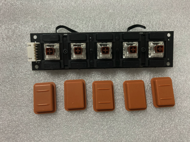
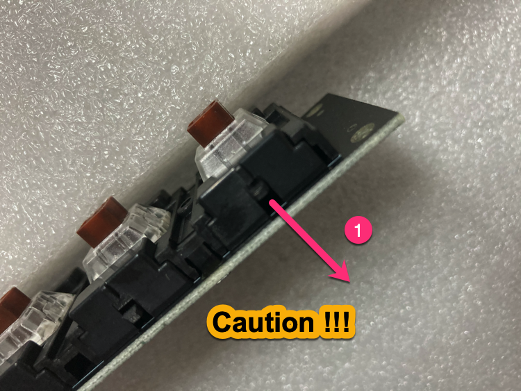
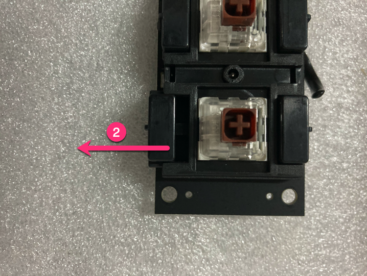
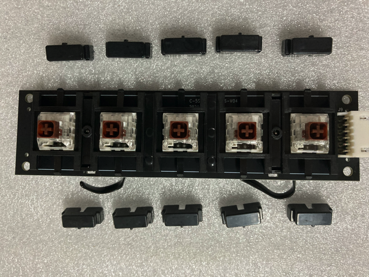
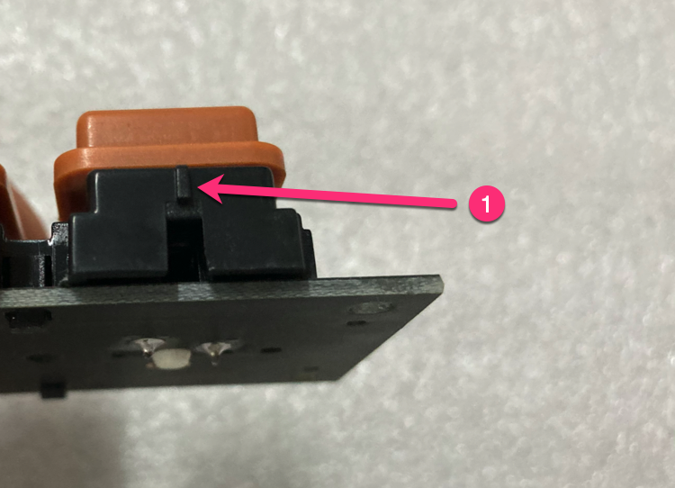
11 Remove 10 limit blocks.
①Push your finger down gently to the position in the picture (TIPS: The distance is about 1mm; Excessive force will cause damage.)
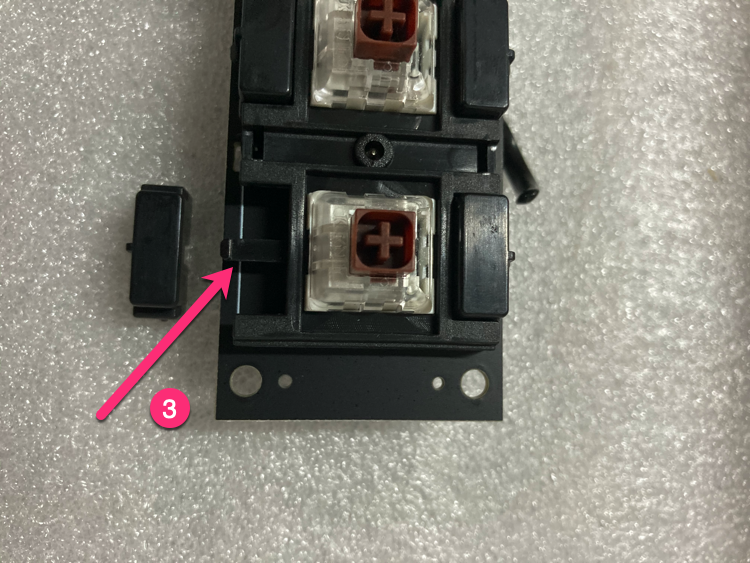
②Push the limit block laterally;
③1 successful, no damage;
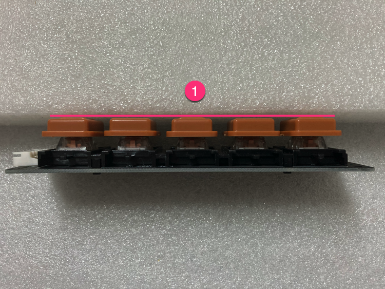
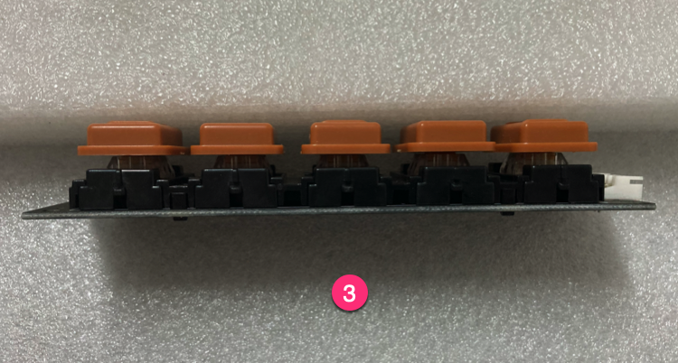
12 Install the keycap to the gold switch shaft PCB.
①After installation, please check the 5 keycaps, the heights should be same;
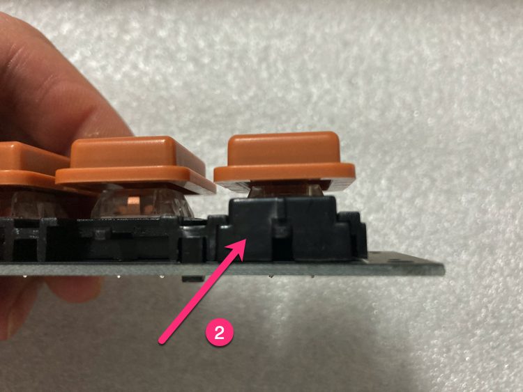
13 Install the limit block.
①Pay attention to the direction;
②1 successful;
③10 successful;
14 Install gold switch shaft PCB.
①There is a 0.2mm gap here. If the keys are rubbed, you can slightly adjust the PCB by left and right, up and down;
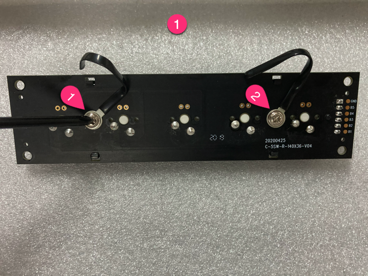
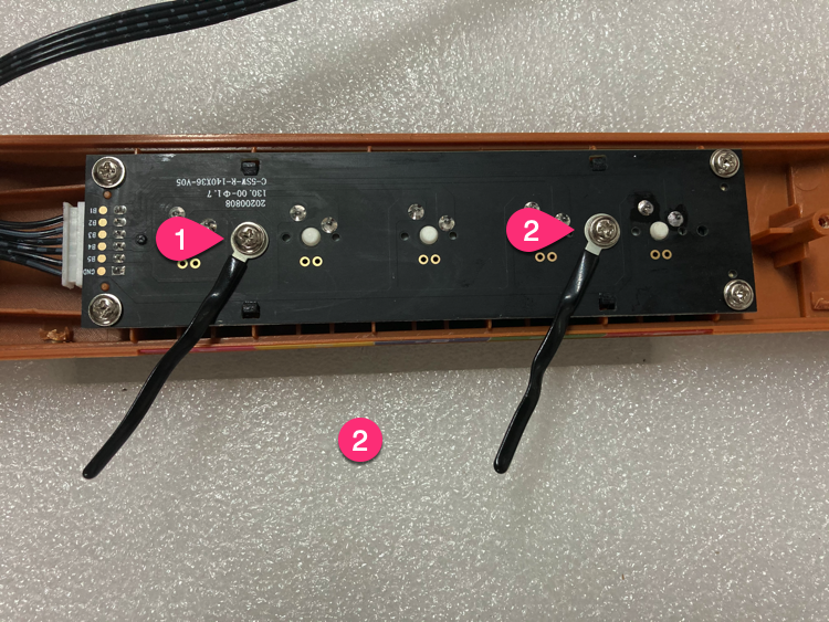
15 Install the wire harness.
①Remove the screws on the original PCB;
②Install it on the new PCB;
16 Install the gyroscope PCB.
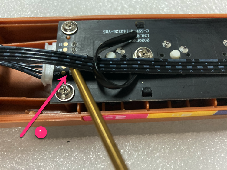
17 Use the wire harness to fix the wire position.
① Note that here, the wire and DIP, left some gaps;
② As shown in the picture, fix the wire;
18 Install the screws.
①Lift the neck of the guitar lightly with your hands, which makes it easier to install 4 screws;
②Tighten the screws by order;
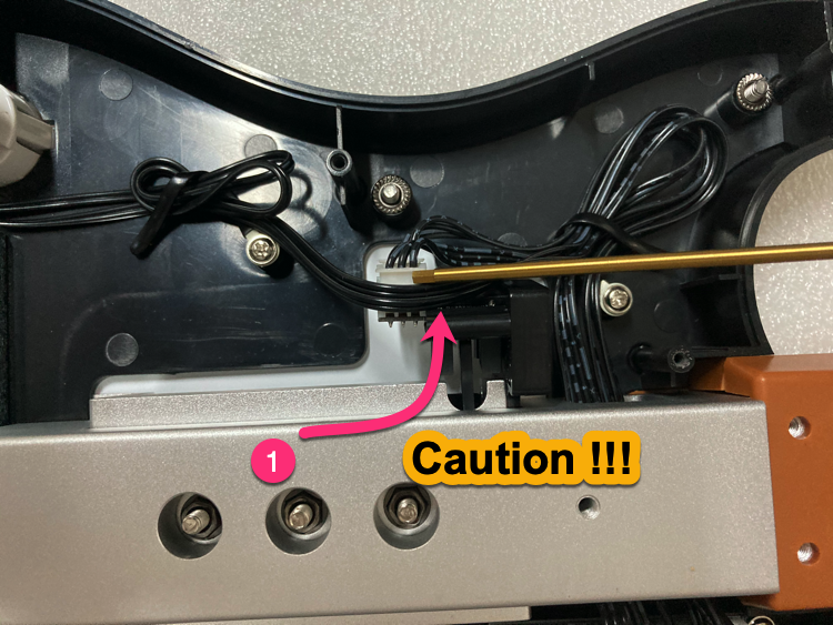
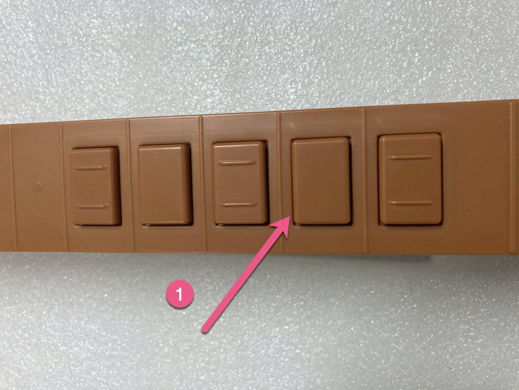
19 Handle Select, Start button wire.
① Please handle the wires of the Select and Start buttons as shown in the figure. (Otherwise, the wire will be crushed.)
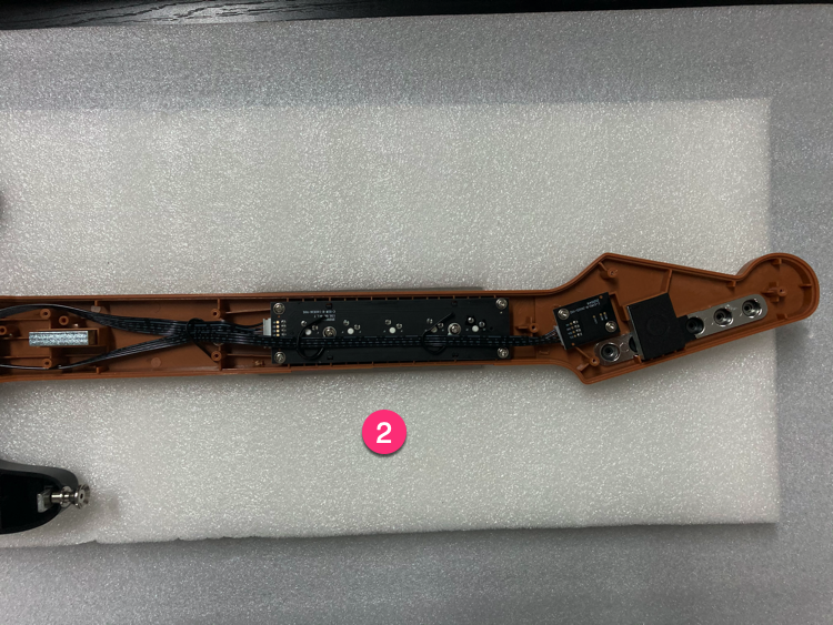
20 Handle the bottom cover.
①Insert 5PIN USB cable;
②As shown in the figure, carry out the wire harness;
③The condition with the bottom cover closed;
21 The order of the bottom cover screws.
③④Don't tighten too much;

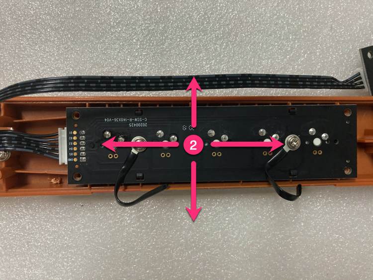
22 The button friction is too large, how to deal with it?
①Try to keep the gaps uniform. If there is obvious friction, please adjust the shaft PCB;
②Shaft PCB, can be fine-tuned 0.2mm in 4 directions;
23 Done
If you encounter a difficult problem, please contact us by email.
Please provide detailed photos and problems, we will reply to you as soon as possible.
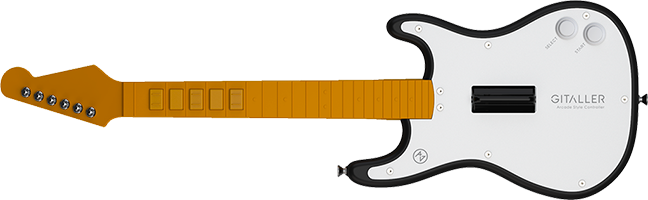
Thank you for purchasing GITALLER.